Hmm. The title does not convey the importance of the subject. How about
"How to make your data to stop lying to you"?
I promised to cover the subject in Truths and lies of your basic racing datalogger.
What is actually the problem here?
As described in that post, there are 2 ways to get your acceleration values: one is through accelerometer's signal ("Proper Acceleration"), and another, through taking a second order derivative of your movement along or across your direction of travel ("GPS Acceleration", for the lack of a better term). As demonstrated in that post, "GPS Acceleration" can only be considered an approximation of what is actually going on. In most cases, very poor approximation indeed, requiring heavy post processing to result in anything resembling actual acceleration, as experienced by your race car and yourself or your driver.
"Proper Acceleration" measurement can have its own problems, it turns out. Here are 2 race cars. In the one on the left, accelerometer is positioned "square" with Longitudinal and Lateral axis of the car (yellow and white axis are aligned). Life is good.
In the one on the right, the accelerometer is rotated (yellow and white axis are not aligned) Now, when the car experiences Longitudinal acceleration, some component of it gets picked up by accelerometer's Longitudinal axis, and some - by its Lateral axis! Same for Lateral acceleration.
So, when you go and examine your data after the fact, you now see that your car has non-zero lateral acceleration when it is driving down the straight!
Here's an example:
Something is clearly not right. The car is driving down the straight yet it shows up to 0.1 G of Proper Lateral acceleration.
Of course, you can add an offset, of, say, -0.1 G, but now it's off in other sections. And, this also means that Longitudinal acceleration is off as well, without any clear indications of how much.
Your logger may offer a tool to calibrate itself to re-align the axis. To be honest, I have seen more cases where it did not work, than the ones where it did, so this is not my preferred way of resolving this issue.
By the way, you may ask, what's the big deal?
Well. I am glad you asked.
If we are talking about basic data logger that only records GPS and accelerometer data, and your Longitudinal and Lateral acceleration data is skewed - even by few degrees - here are types of analysis you cannot do, since your results will range from meaningless to dangerously misleading:
- Everything except staring at GPS Speed trace and your lap/segment times.
And here are types of analysis you can still do with skewed accelerometer data:
- Staring at your GPS Speed trace
- Lap/Segment times
I hope you enjoy staring at your GPS Trace... You can actually get a lot of useful info out of Segment times analysis, so there's that.
Do you want to look at brake application profile? Engine performance? Cornering grip? Sorry, your results will be off, possibly to the point your analysis is hurting more than helping. Garbage in, garbage out, and all that.
Luckily, this is fairly straightforward problem to fix
We will be using math channels, and applying some high school geometry.(https://en.wikipedia.org/wiki/Rotation_(mathematics) - see "two dimensions section"). You remember your two dimensional vector rotations, don't you?
OK, here's how to set it up.
Let's use AiM Race Analysis. After all, AiM solo is nearly 100% likely to be mis-oriented to the axis of the car it is mounted on... When you make something too easy, you run the risk of making it too easy to get it wrong.
By the way, this assumes that the accelerometer is, at least, aligned vertically (i.e. not tilted up/down, or, Euclid forbid, is lying down "on its face").
If not, the principles are similar, but you will have to correct in 3 dimension. Easy, right?
So, here we go.
Step 1.
Load up the session and create 2 “X-Y Plots”: Click “X-Y Plot” button, then select “create new”, instead of “activate existing”. Do it twice.Step 2.
Now, click on the windows resize button, to make the UI allow you
to lay out all windows (instead of default single-tabbed-window view). For reasons we will never understand, that button is called "Restore-Down"...
Step 3.
Step 4.
Step 5.
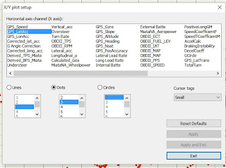
Select "GPS_LatAcc", or whatever it is called on your AiM logger as X axis.Step 6.
Make sure you have same X-Y Plot selected (click anywhere within plot area). Now, in the "Measure list", on the left, select "GPS_LonAcc", and un-select everything else.
A. "G Angle Correction"
B. Corrected_lat_acc:
C. Corrected_long_acc:
"Formula" value to copy/paste:
Longitudinal_a*cos(DEG2RAD*G Angle
Correction)-Lateral_acc*sin(DEG2RAD*G Angle Correction)


No comments:
Post a Comment